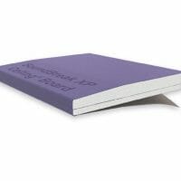
SoundBreak XP®
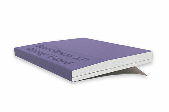
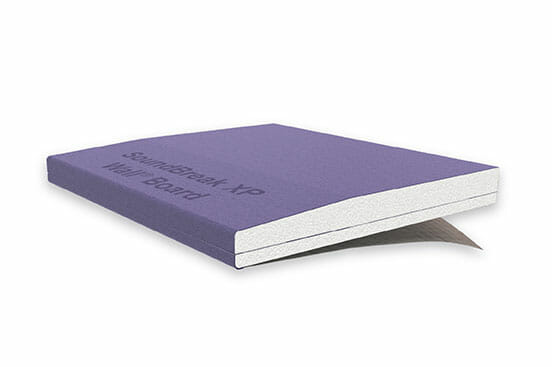
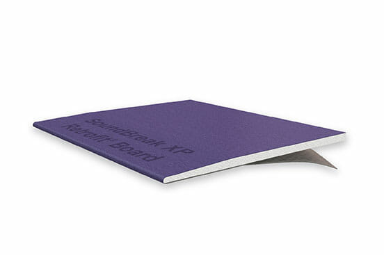

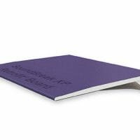
SoundBreak XP Acoustically Enhanced Gypsum Board
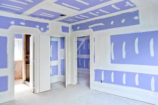
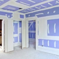
Turn down the noise when you incorporate SoundBreak XP® Gypsum Board into your wall or ceiling assemblies. You will dramatically reduce sound transmission between rooms or dwelling units with this superior sound-damping gypsum board.
SoundBreak XP has an acoustically enhanced, high-density gypsum core encased in heavy, abrasion and mold/mildew/moisture resistant, 100% recycled PURPLE® paper on both sides. Plus, SoundBreak XP provides superior mold-inhibiting qualities.